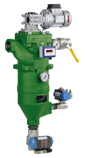
AF 113 G backflush filter
DOWNLOAD PDF
INDUSTRIAL MARKET
Plastic – Paints
These compact, inline filter systems are designed for automatic cleaning. The system is cleaned by rotating the filter element and backflushing with internal pressure media.
Cast design with internal pressure cleaning and integrated cyclone effect
Multiple advantages
Extended filter
Extended filter service life due to the use of a cleanable element
No interruption
Cleaning is possible without interrupting filtration
Separation quality
Precise separation quality in accordance with the metal-edge principle
Top-quality
Top-quality, asymmetric filter medium made of multiple-sintered stainless steel fleece on a rugged core element
Efficient cleaning
Efficient filter cleaning assures maximum process stability
Long service life
Solid construction and high-quality materials for a long service life
Minimal loss
Minimal liquid loss during cleaning
Shaft seals
Gas-tight shaft seals available optional
Backflush pulse
Filter cleaned one segment at a time with a high backflush pulse
Indicator
Actual filter rating and nominal separation are indicated
Integrated preseparation
Integrated preseparation thanks to tangential inflow and preseparator tube
Wide range of applications
Material variants open up a wide range of applications
Modular system
Filtration Group modular Vario system for optimum filter selection
Application in Ex zone
Application in Ex zone 1 and 2 optional
Maintenance
Easy maintenance
Operating principle
The Filtration Group (ex Mahle) AF 113 G backflush filter belongs to the Vario series. The compact Filtration Group automatic filter system is used for fine and micro-filtration of a variety of low-viscosity liquids.
This inline pressure filter consumes no filter material, which means there is also no need for subsequent disposal. The filter is cleaned without interrupting operation. The concentrated solids are drained off simply by opening the system for a short time.
The medium to be cleaned is guided into the filter housing under pressure and flows inward through the Filtration Group segmented element. Particles settle on the surface of the filter medium. The filtered fluid exits the filter housing at the top opposite the inlet connection.
The integrated preseparator relieves the load on the segmented element, particularly from coarse and heavy particles. This is achieved by a tangential flow around the preseparator tube and the deflection edges.
The filter is cleaned when a preset differential pressure limit, a set interval or a defined filtered fluid quantity is reached. The segmented element is turned as the cleaning valve is opened. The segments are then guided one at a time past the flushing channel on the outer circumference, causing them to open and close alternately. The internal pressure is built up at a throttling point downstream of the filter, so that when one segment opens, an outward surge cleans the separated particles from the filter material. As a result of this pulse cleaning principle, the particles are catapulted out, collected in the flushing channel and discharged with a small amount of internal medium. One turn is sufficient to clean all segments. The residue that has settled in the collection cone can be emptied via the drain valve either when the machine is at a standstill or during filtration.
All filters of the Filtration Group Vario series are protected by various patents.
Good cleanability due to asymmetric design
High free surface portion
Defined particle retention
Several material combinations possible

Higher contamination levels because of pleated filter area
Complete stainless steel
Higher flow rate compared to standard elements
Specially for filter fineness < 60 µm
Filter media (wire mesh) made of 1.4401


Technical data
Connections and nominal diameters:

Materials:

Use the form to request our product
— Viscosity in 1 mm²/s
— Viscosity in 33 mm²/s
— Viscosity in 100 mm²/s
— Viscosity in 500 mm²/s
y = volumetric flow V [l/min]
x = gap width f [µm]
The curves represent the volumetric flow through the entire filter system (filter housing including one filter element as an example) and refer to a differential pressure of 0.3 bar. Specific information about process data is essential for reliable operation of automatic filters.